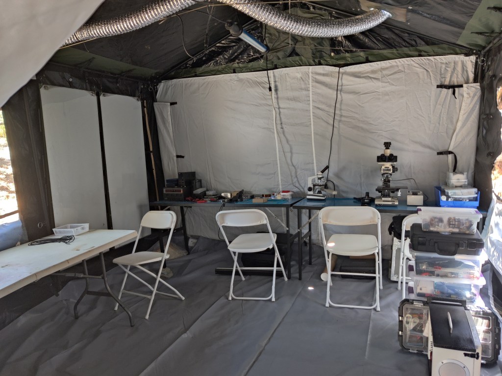
It’s that time of year again, school’s out for summer and I’m headed out to Grindfest for a week of biohacking in the desert! This year I had a single week between coming home from school and leaving for Tehachapi. Not to mention, I fit in a trip to PCB East right before I came home! I still wanted to throw something together as Project Output sadly wasn’t ready enough to demo. A goal for this summer is working on my rapid prototyping skills. It’s very hard to purposely limit the scope and polish of a project in order to have something rather than nothing. I tend to fall victim to scope creep, but don’t we all!
Inspired by Adam Savage’s One Day Builds, I set out to finish my Infrared Vein Viewer project just one day before leaving. This fool’s errand started Saturday night and I managed to finish the hardware components by Sunday at 11:00PM ahead of my 4:30AM morning Monday!
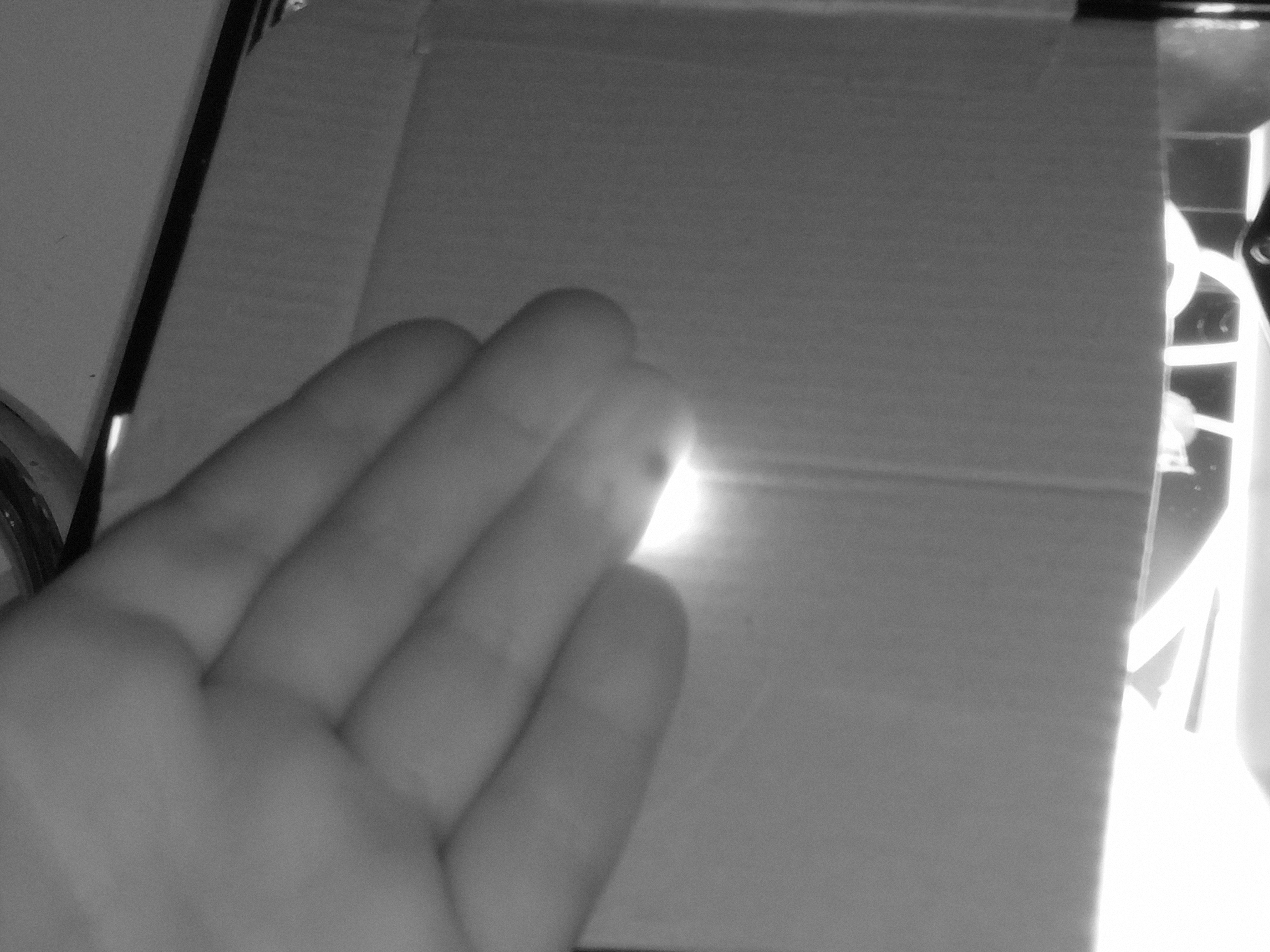
The theory behind the project is based on the permittivity of skin, bone, and blood at differing wavelengths of light. IR vein viewers are becoming more common in hospitals to allow for easier IV placement and blood draws. These usually re-project the image onto the skin providing a very cool view of what’s inside! I planned on using this one specifically to help with implant placement in difficult areas on the extremities. While skin is relatively transparent to infrared light, thicker body parts don’t fare as well. I had a few design requirements. It needed to be portable, have a built-in display or some form of live camera view, and be large enough and powerful enough to image a whole hand at once.
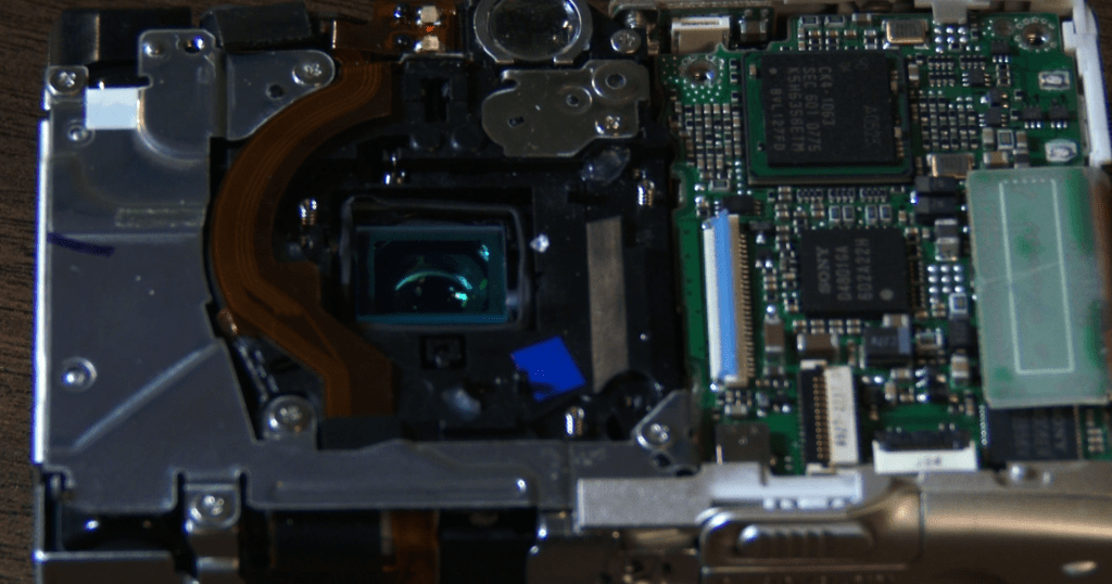
This project started quite a while ago and the initial IR capture device was an old Canon point and shoot camera that I had removed the IR filter from. This allowed it to capture full color as well as infrared. I still have the camera and while the battery is old and the image isn’t HD, it works quite well! I have updated the camera however to the Raspberry Pi NoIR Cam. This does the same exact thing, but at a fraction of the size, with the option to output the image to a larger display live. I settled on using a Pi A+ that I wasn’t using for anything else. Despite the low power and its age, it works perfectly fine for what I’m using it for.
The concept requires a high-powered IR source, and initially I planned on using a homemade panel of 5mm IR LEDs. Somewhere between the first go around 2 years ago and sitting in my project bin, I burnt out all the of them and cut off part of the perfboard for another project. Thankfully, LED technology has advanced quite a bit since then with COB LEDs becoming readily available. I found a 30W 850nm while searching AliExpress, that looked perfect. I planned on using my ancient benchtop power supply, but I ended up tripping the internal breaker in the process!
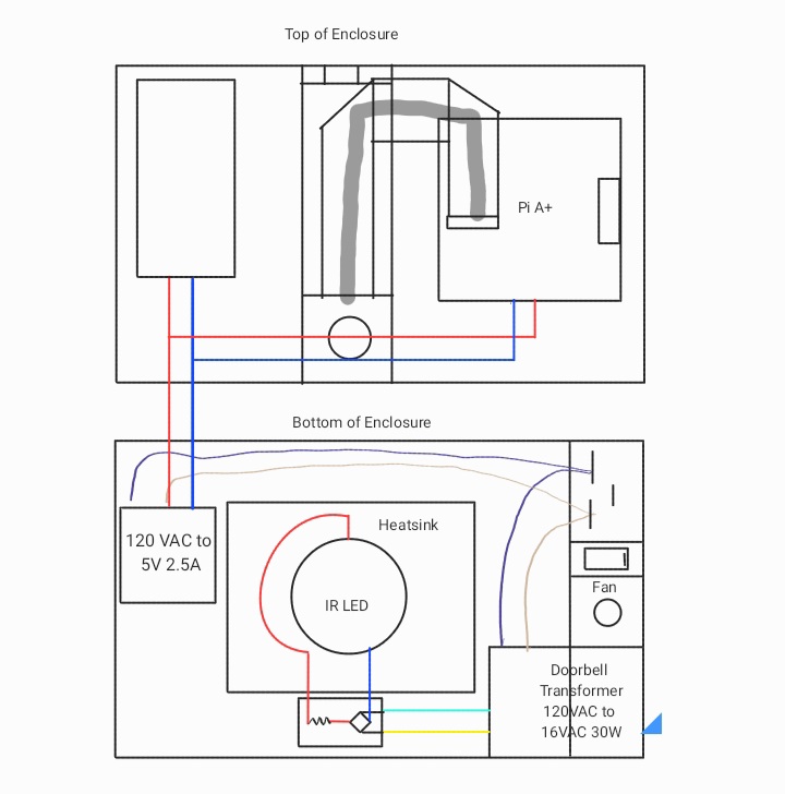
Stumped for a next option, I looked into LED and Halogen drivers available at Home Depot locally. While searching, I found the perfect solution in a 16VAC 30W doorbell transformer. Exactly the specs listed in the 10-line text file the seller called a datasheet! I’m not used to this level of luck, so I doubled checked my math and planned out the circuit pictured below. I used a pc power supply plug for power in with a built-in switch. This is split between the transformer and a disassembled 5V 2A wall wart for the Pi. I thankfully had a bridge rectifier IC on hand to attach to the output of the transformer which in turn is connected to the LED. I know I should’ve added a current limiting resistor, but I didn’t have any rated over 1W, so I’m hoping the parasitic resistance of the larger gauge wire is adequate. I am driving it at exactly the rated voltage and current, so I’m not terribly worried! The other parts depicted are the LED heatsink, which is very necessary given the wattage, and the camera arm.
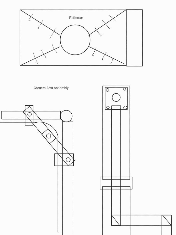
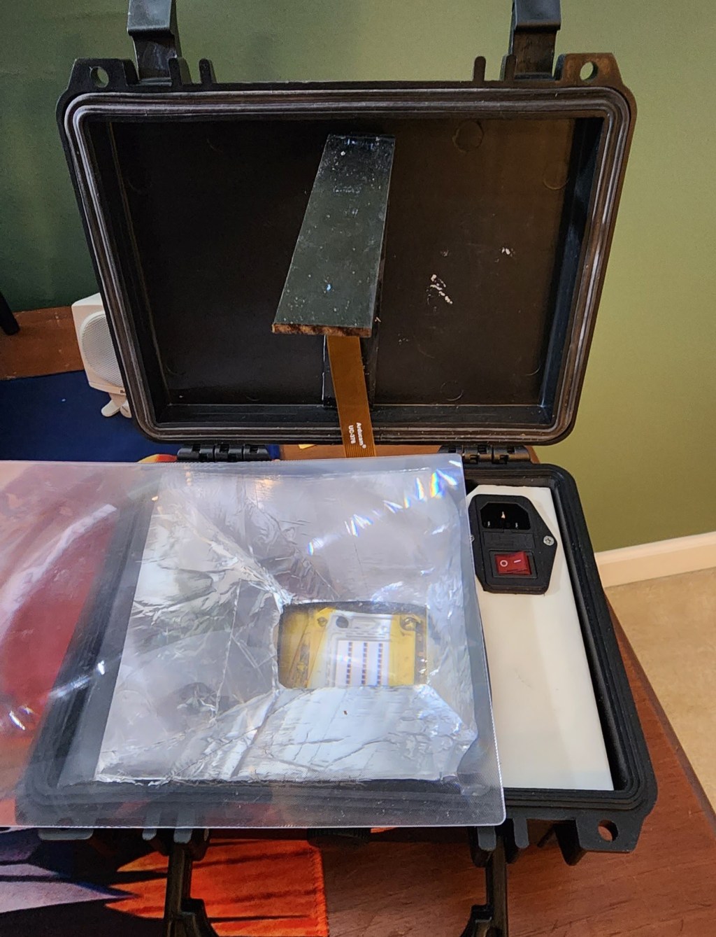
I needed a few other parts to tidy up the box. First was a reflector, both to direct the light better and to hide everything underneath it! I simply cut and taped together cardboard covered in aluminum tape. I plan on revisiting this when I have the luxury of more time. I also added a plastic spacer to mount the plug in as well as help position the sheet of Lexan. This was made out of a scrap of plastic curtain bar, It fit just right! Lastly, I wanted to add an arm to mount the NoIR camera onto. The plan was to attach it to the upper lid and have it swing upwards to 90º. I painted a few paint stir sticks black and added a hinge. Doubled sided tape was all I needed to mount the camera and the ribbon cable. I didn’t manage to find a solution to the slightly floppy hinge before I left, but I plan on adding a kickstand and 3D printing a locking mechanism at a later date.
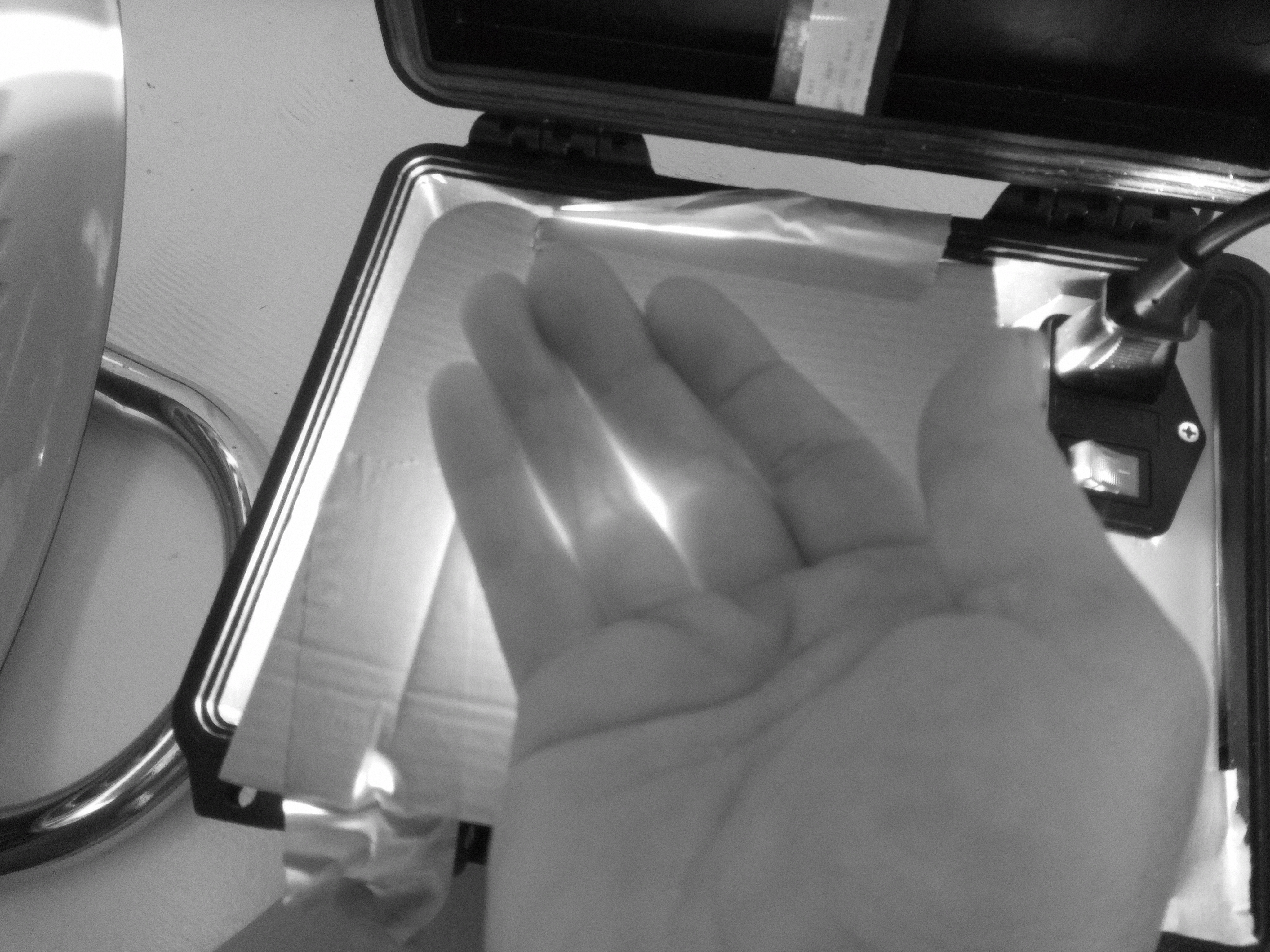
I got too used to my good luck, when soldering the output wires onto the rectifier board, I swapped the polarity. When I powered it on to check, all I got was a puff of smoke and a very angry sounding transformer! I was terrified that I damaged the LED. Thankfully, it wasn’t harmed, but the rectifier was toast! I only had one more, and after swapping it out and praying to James Clerk Maxwell himself, I tried one more time. While the soldering wasn’t anything I’d ever show a single soul, it powered on and worked beautifully! I attached everything to the case with double sided tape and simply press fit the Lexan over top.
The software to control the camera over the CSI connection changed between the buster and bullseye releases of Raspbian, so I had to refamiliarize myself with the controls. libcam has quite a few more features than raspivid did, but quite honestly, I won’t use any of them! All I need is for it to run on start up in full screen mode and output the feed over HDMI. Working with the libraries caused some issues. The NoIR cam was being horrendously overexposed! Not to mention, the AC power supply was causing strobing even after the rectification. This was causing black bars to show due to the rolling shutter.
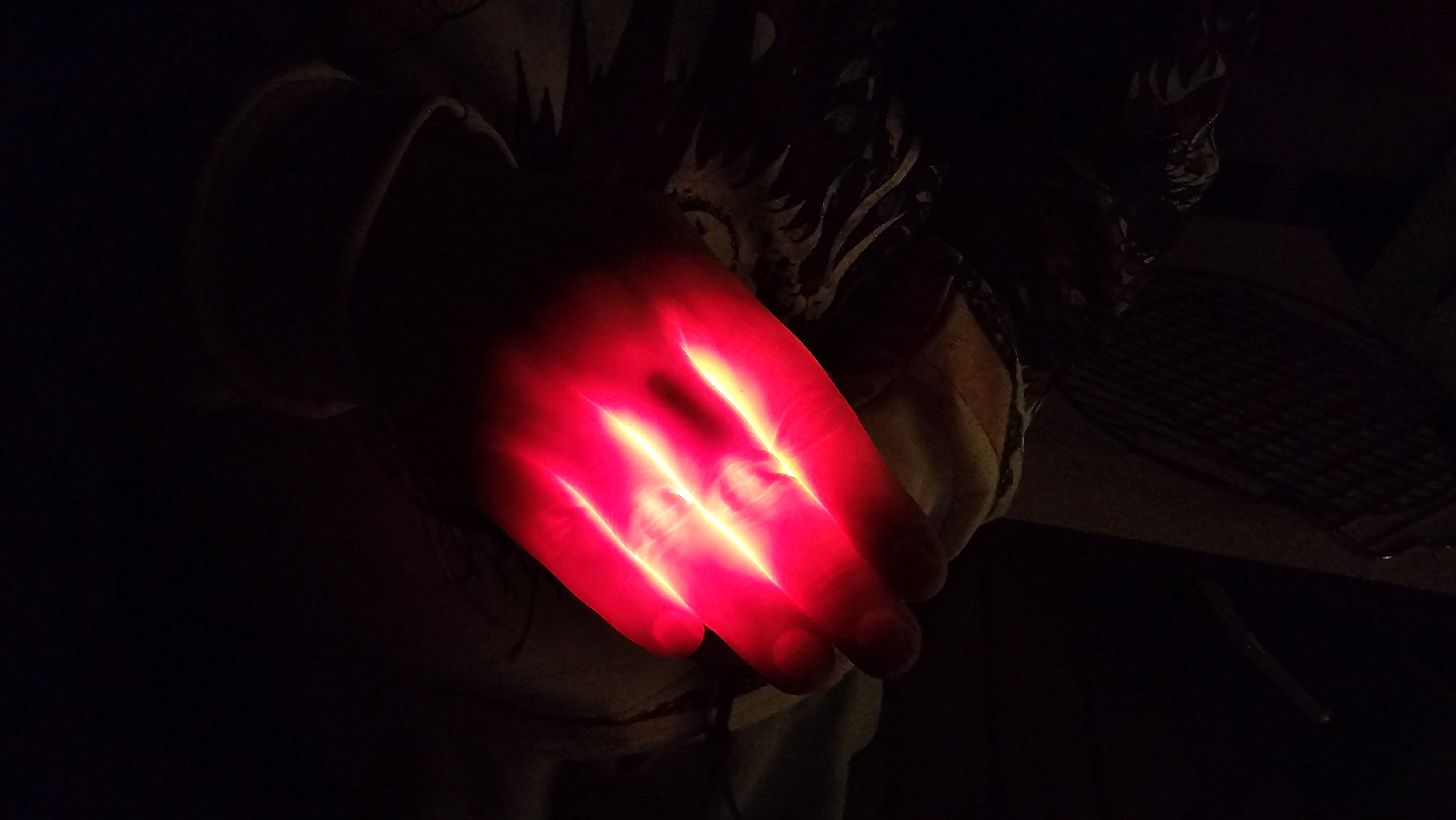
Luckily a friend, the 24 Hour Engineer brought his backup phone that had an IR camera built in! We managed to get some awesome shots of my finger magnet, a flex implant, and some decent vein pictures!
The end result was some awesome pictures and plenty more ideas on how to improve the design. Here’s the roadmap for the future if I decide to improve it!
- Masking layer to block out the extra light
- Lens to focus the light into a smaller area
- Intensity control for the IR array
- Better DC power to the LED panel to eliminate the rolling shutter issues
- Shade to block outside light
- Different IR camera module or a better camera arm setup, we struggled to get it to image a whole hand
- Active region masking using a transparent LCD
I consider this project a success! Everything I do is working towards being a better engineer and maker, and sometimes making something that just barely works is worth so much more than a design that languishes in the planning stages. Hopefully I’ll have the chance to improve my workflow and increase my output this Summer!
I had such a great time at Grindfest this year. It was great to see everyone and the IR project was just the tip of the iceberg. Stay tuned in the coming weeks for more info on the projects we’re working on!